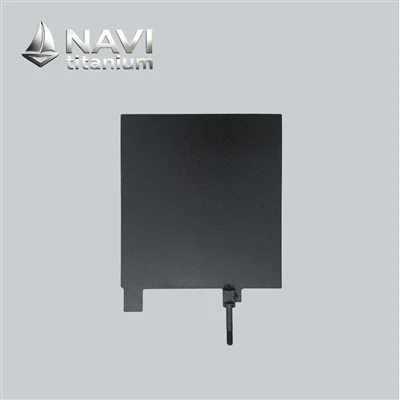


NAVI Titanium ruthenium iridium titanium anode plates combine a high-purity titanium substrate with a ruthenium-iridium oxide active layer. As dimensionally stable electrodes, they are intended for continuous use in saline, acidic, and high-load electrolytic conditions. NAVI Titanium flat geometry allows controlled positioning and straightforward electrical attachment, making this format suitable for water treatment, chlor-alkali electrolysis, and other industrial electrode applications.
Solution of NAVI Titanium
Seawater lines, brine circuits and plating baths discard anodes for different reasons, so one formulation serves none of them well. NAVI Titanium specifies a plate backwards from your bath: the Ru:Ir ratio governs how readily chlorine leaves the surface, noble-metal loading governs how long that keeps happening, and plate gauge decides how much of the face is worked before current thins at the edges. Outlines, hole patterns and tab positions are cut to drawing rather than trimmed from stock. Dimensions ordered most often are collected in the NAVI Titanium Advanced MMO Tiatnium Anode table below.


NAVI Titanium has developed specialized ruthenium-iridium titanium anode plates for demanding chlorine and oxygen evolution duties. The Ru-Ir oxide layer provides an active reaction interface for transferring electrical charge and promoting the intended anodic reaction. Their planar form also allows the electrode area, terminal location, and spacing to be adapted to different reactor layouts.


Application
These planar conductive components from NAVI Titanium are extensively employed in chlor-alkali production and electrochlorination installations where precise positioning of current-carrying elements is essential. Their flat profile allows accurate spacing control, orderly installation, and effective utilization of reactor volume. This layout facilitates consistent alignment of conductive assemblies while enabling flexible integration into large-scale electrolytic units, making the format well suited for both high-capacity membrane cells and compact chlorine-generation installations.
Current-delivery elements used in chlor-alkali production are developed according to the construction requirements of large electrolytic cells, where numerous ruthenium iridium titanium anode plate units operate within carefully planned arrangements. The flat form enables engineers to establish uniform positioning, maintain controlled intervals between adjacent components, and organize internal cell volume more effectively. In large membrane-cell installations, this planar layout simplifies mechanical assembly while supporting standardized fabrication procedures during unit construction. By creating a clearly defined reaction interface, the component allows manufacturers to coordinate electrical terminals, supporting frameworks, and cell dimensions according to individual production objectives. Consequently, this arrangement is particularly suitable for continuous manufacturing environments requiring repeatable component placement and well-organized installation architecture.


Electrochlorination units depend on continuous interaction between flowing electrolyte and active reaction interfaces to produce oxidizing species on demand. Planar conductive elements establish organized reaction regions that promote relatively balanced liquid distribution throughout compact reactor chambers. Engineers often coordinate inlet positioning, outlet flow-path layout, and component orientation simultaneously, as hydraulic behavior has a direct influence on electrolyte residence time within the electrolytic cell. This integrated technical arrangement supports compact installations for production-scale water treatment applications without requiring overly complex reactor architectures, while also allowing easier maintenance access, modular expansion, and improved adaptability across different operational environments and system configurations.
Purchasing guide

Quality control(QC)
Every plate leaves an ISO 9001 line under a lot code that stays readable after installation. Noble-metal loading, coating thickness, adhesion and accelerated-life figures are logged against that lot, never averaged over a month of output. Press the button below to open our COA and read the actual test values for the batch heading your way.
| Certificate of Analysis | ||
| Titanium Base Material Suppliers: | Coating Precursor Suppliers: | COA of product: |
|
|
|
|


Manufacturing Process
A plate misbehaves in ways a rod never does. Current crowds along its perimeter and around every drilled hole, and thin titanium relaxes each time it goes back through a firing cycle. The line below is arranged around those two facts, and nothing leaves for assembly before the last check.
1. Plate Stock - Grade Choice and Cutting Order
Blanks are cut from Gr1 sheet unless the drawing demands the stiffness of Gr2; Gr1 keeps iron out of the interface and accepts expansion into mesh without edge cracking. Every hole, slot and tab is finished at this stage, before any oxide exists. Once a film has been fired, cutting or punching tears it off the hole wall - and that is where a plate begins dying first.
2. Edge Conditioning - Where Plates Actually Wear
Current concentrates at boundaries, so the perimeter loses its Ru-Ir film while the centre still looks untouched. Corners are radiused, holes deburred, then those zones receive extra brush passes so more active material sits where the load runs heaviest. Ignore this step and the symptom arrives late: the face appears intact, yet cell voltage climbs because the working border has quietly gone.

3. Degrease and Etch - Grip Before Chemistry
Blanks are alkaline-degreased and then etched in hot oxalic acid until the surface is matte and mechanically keyed. Coating losses usually trace back to preparation rather than formulation: a trace of rolling oil bakes into a barrier, electrolyte creeps behind it, and the layer lifts in service looking nothing like a chemistry problem.
4. Stress Relief and Flatness Control
Each pass through a 450 °C chamber lets 1–2 mm titanium relax, and a warped plate opens an uneven gap to the cathode, concentrating output on the closest inches. We stress-relieve after cutting and re-flatten between firing stages. Shape is settled here, not corrected at the tank with shims and force, since bending a coated plate cracks brittle oxide.

5. The Ru-Ir Film - Mixed Solution, Many Thin Fires
Precious solution is blended to a Ru:Ir ratio set by duty: ruthenium-rich for chlorine evolution in seawater and brine, iridium-bearing where oxygen evolution and long campaigns dominate. It goes on in thin brush or roll passes, each one decomposed at temperature before the next follows. Total noble-metal loading per square metre is agreed at quotation and confirmed afterwards rather than assumed.
6. Mapping the Face, Plus Life Testing
XRF readings are taken at several points per plate - centre, corners, edge bands - because one reading mid-face hides poor circulation near the boundaries. Thin spots trigger rework or scrap. Remaining parts go through thermal shock, adhesion, potential and accelerated-life testing in an acid bath, all recorded under the lot code printed on the part.

The busbar tab stays masked and bright; a coated contact face adds resistance exactly where the joint must run cool. Finished plates are interleaved and corner-guarded so they arrive flat and stack flat, with lot codes readable from outside the carton so stores can identify batches without opening packs. Photographs of the packed crate go out before dispatch.
Application

Electrical field distribution across plate anodes is closely associated with current entry points, conductive routes, and changes in surface geometry. Areas near connectors, corners, or structural transitions may experience different electrical conditions due to variations in pathway concentration. To address these challenges, engineers increasingly apply numerical analysis methods to evaluate potential distribution before physical production. Simulation models help identify regions where adjustments may be required, allowing modifications to plate dimensions, connection arrangements, or active surface layouts at an early development stage. Combined with prototype verification, this approach provides a deeper understanding of electrode behavior under practical conditions and supports the creation of plate configurations suitable for specialized electrolytic equipment with demanding operational requirements.
The active area configuration of a ruthenium iridium titanium anode plate refers to the planned arrangement of functional reaction surfaces and reserved sections across the flat electrode structure. Unlike simple dimensional design, this approach considers how different regions contribute to electrochemical operation within the complete assembly. Certain areas may be intentionally excluded from the active surface to accommodate electrical connections, mechanical supports, insulation requirements, or protective interfaces. By defining these zones in advance, engineers can establish a clear relationship between reaction areas and auxiliary sections, allowing the plate structure to better match specific equipment requirements. This selective arrangement is especially valuable for industrial systems where space utilization, connection methods, and electrode positioning must be coordinated during the design stage.


Different installation layouts may require continuous active interfaces, segmented reaction areas, or customized catalytic patterns depending on electrolyte flow paths and electrical connection methods. By defining functional zones according to reactor spatial arrangement, manufacturers can produce anodic components that simplify assembly while maintaining consistent spacing between adjacent elements. This technical approach provides greater adaptability for customized production units and supports future modifications without fundamentally changing the mechanical framework of the electrolytic installation. Such flexibility is especially valuable for projects involving capacity expansion, process adjustments, or upgraded reactor assemblies.
Modern electrolytic assemblies increasingly consider the anodic element as an integrated mechanical component rather than a replaceable accessory. During reactor development, engineers evaluate mounting methods, support positions, electrical terminals, sealing interfaces, and maintenance accessibility simultaneously. NAVI Titanium manufactures planar conductive components with features such as precision-drilled openings, welded terminals, reinforcement sections, or customized edge profiles to satisfy the mechanical requirements of specific installations. These physical adaptations contribute to streamlined assembly procedures and enhance compatibility with modular production-scale units, under diverse operating conditions worldwide.


Mechanical integration also affects long-term maintenance strategies. Standardized connection points and interchangeable mounting dimensions allow replacement operations to be completed without extensive modification of surrounding parts. This modular approach lowers maintenance complexity while enabling manufacturing facilities to expand or upgrade installations through compatible component arrangements developed from the same mechanical platform. In addition, standardized fabrication methods help maintain consistency during repeated project implementation. Such design coordination also facilitates inventory management, simplifies technical documentation, and supports faster response during equipment servicing. By establishing predictable assembly relationships.
Dimensional consistency plays an essential role in maintaining uniform spacing throughout large electrolytic assemblies. Variations in flatness, thickness, opening position, or edge profile may influence installation efficiency and affect the alignment of neighboring components during unit assembly. Therefore, NAVI Titanium incorporates incorporate multiple inspection stages to verify machining accuracy before functional layer treatment and final catalytic layer application begin. Precision fabrication supports dependable integration across both standard ruthenium iridium titanium anode plate products and project-specific conductive element layouts, while reducing unexpected adjustments during installation and commissioning stages.


Dimensional verification extends beyond basic length and width measurements. Manufacturers commonly evaluate flatness, parallelism, mounting tolerance, terminal alignment, and physical repeatability across production batches. These parameters become increasingly important in large-scale installations where numerous planar anodic components operate within a shared mechanical framework. Maintaining consistent dimensions simplifies assembly processes while improving manufacturing repeatability for customized technical projects. Through controlled fabrication methods, we can achieve reliable compatibility between individual components and complete electrolytic assemblies, supporting efficient integration, reduced adjustment requirements, and predictable operational performance during extended service periods.
NAVI Titanium Advantage of Receiving at Site
At NAVI Titanium, we view site receiving as an important handover point between shipment and field setup. When your electrode arrives, your team can first examine the crate or carton for crushed corners, punctures, leaning, moisture marks, or signs of movement inside the package before opening it. We recommend photographing the package condition, particularly for project shipments that pass through several handling points. Once opened, the unit should be lifted carefully rather than pulled by a lead, tab, or fastening point. The active area should not be placed directly on concrete floors, steel benches, or rough temporary supports. A clean padded sheet or dedicated tray provides a safer location for short-term handling while the incoming inspection is completed.


For customers receiving anode at an active project site, NAVI Titanium recommends checking more than quantity alone. Your team can compare the delivered plate with the approved drawing, identification marks, dimensions, and accompanying inspection documents. Visual attention can be given to edges, drilled holes, corners, tabs, and mounting points, where unintended pressure may become noticeable after transportation. If several plates are included, keeping each piece with its corresponding identification can prevent similar items from being mixed during unloading. Any unusual mark, bent portion, displaced fitting, or packing-related concern can be photographed before the item is moved again. These records give your purchasing and project teams a clearer reference if clarification is needed and avoid unnecessary handling before the plate reaches its intended position.
After the initial check, we recommends moving the ruthenium iridium titanium anode plate to a temporary holding area rather than leaving it beside active installation work. The location should be clean, dry, shaded, and separated from loose metal fragments, welding debris, grinding dust, and other workshop materials. If the plate needs to be transferred again, suitable padded supports or designated holding points can be used instead of gripping the working portion with tools. Where practical, the original wrapping can remain around unused areas until installation preparation begins. This is particularly helpful on busy project sites, where components may otherwise be shifted several times before installation. By considering the receiving process in advance, we helps customers maintain clearer records and reduce unnecessary handling between delivery, inspection, temporary holding, and installation.

FAQ
How do I select the right titanium anode plate for my electrolysis process?
+
-
Selection should be based on the electrolyte composition, chlorine or oxygen evolution requirements, current density, operating temperature, plate dimensions, and expected service period. We can recommend a suitable plate specification and Ru-Ir formulation after reviewing the actual operating conditions.
What maintenance is required for a titanium anode during regular operation?
+
-
Routine inspection should focus on electrical connections, deposits, discoloration, dimensional changes, and signs of mechanical damage. Keeping the electrolyte within the specified operating range and preventing unnecessary contamination can help maintain consistent electrolysis performance.
How long can a ruthenium iridium titanium anode plate typically be used?
+
-
Service life varies with current density, electrolyte chemistry, temperature, operating frequency, and process control. A plate used under suitable conditions can provide extended service, while excessive current loading or aggressive chemical conditions may accelerate consumption of the active material.
How can I determine when a titanium anode plate needs to be replaced?
+
-
Replacement should be considered when operating voltage increases noticeably, electrolysis output declines, visual damage becomes apparent, or the active material has been significantly consumed. Comparing operating data with the original performance is generally more useful than relying on a fixed replacement schedule.
What quality information should I request before purchasing a titanium anode plate?
+
-
Customers should verify the titanium grade, Ru-Ir formulation, plate dimensions, active material loading, electrical characteristics, inspection records, and available quality documentation. For customized orders, operating conditions should also be confirmed before production to ensure the supplied plate matches the intended process.
Hot Tags: ruthenium iridium titanium anode plate, China ruthenium iridium titanium anode plate manufacturers, suppliers, factory, DSA Electrode, Insoluble Anode, MMO Titanium, Platinized Titanium Anode, Platinized Titanium Mesh Anode, Titanium Anode Mesh Basket