
Every millivolt of voltage loss in PEM water electrolysis technology costs more and uses less energy. The titanium anode-catalyst layer interface is one of the most overlooked performance-improvement areas. Bad interface design delays mass movement and increases electrical resistance, making your hydrogen-producing system less efficient.
In extreme acidic conditions, modern PEM electrolysers demand anodes with strong conductivity and minimal overpotential. Choosing the correct materials and ensuring the base, coating, and membrane electrode structure function together is difficult. Interface engineering advances have demonstrated that clever design improvements may reduce voltage losses by 50–120 mV at typical operational current densities. This boosts system efficiency.
You must consider numerous factors, including surface shape, substrate porosity, transition layer composition, and catalyst binding, to understand how interface design influences electrochemical performance. Each section works independently to reduce resistance routes and speed charge transfer.

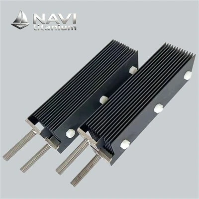
1.Specification
General Shapes: Plate, Rod, Mesh, Tube or customization
Coating: The classical formula of IrO2-Ta2O5, Ru-Ir, Pt, or customization
Electrochemical reaction: Oxygen/Chlorine/Hydrogen evolution reaction
Internal Code: NAVI-1-001
Brand: NAVI Titanium®
Basic Material: Pure Titanium Gr1
Advanced fields of NAVI: PEM, PCB, wastwater treatment etc.
2.Purchasing guide
(1)Process
NAVI Titanium(since 2008) can process according to your design drawings
(2)Free sample
NAVI Titanium supply free sample for general specifications
(3)Technology support
Professional one-for-one service, design free, welcome to contact us
How Does Titanium Anode Interface Design Reduce PEM Electrolyzer Voltage Loss?
Lowering voltage loss involves reducing interfacial resistance at all anode contact locations. Electrons go from the outside circuit to the titanium anode substrate, via multiple material barriers, and to the catalyst active sites, where oxygen evolution occurs, in a PEM electrolyser. Contacts provide potential barriers that prevent electrons from travelling, and poorly designed junctions may cause voltage dips and resistance hotspots.
Voltage loss in PEM systems is generated by many anode contact events that are interconnected. Contact resistance between titanium substrate and catalyst coating is the main culprit. Subsurface oxidation layers, micro-gaps during operation, and catalyst delamination are further culprits. Researchers from major electrochemistry schools discovered that natural titanium oxide coatings may increase contact resistance by 20-40 mΩ·cm², significantly impacting cell voltage over 2 A/cm².
Titanium substrate surface microstructure is also crucial. Smooth, polished surfaces exhibit more contact resistance than textured surfaces, which is odd. This is because the catalyst layer contacts less of their surface. The apparent conflict disappears when you consider how regulated surface roughness increases the actual contact area and offers mechanical anchoring sites to prevent coating delamination under continual temperature and mechanical forces.

The Role of Surface Energy in Interface Quality

Surface energy matching between the titanium base and coatings influences adhesion and electron flow. Titanium naturally develops a passivating oxide layer in air or water. This creates a high-energy surface that many coatings can't attach to. These two items don't bond well together, gaps occur, and they break down quicker in the anode compartment's oxidative environment.
Advanced surface procedures transform titanium's surface chemistry to make it compatible with precious metal catalyst layers. Plasma treatment, chemical etching, and thermal preparation affect surface energy patterns. This improves coating adhesion and electronics connectivity. Field data from operating PEM sites reveals that adequately surface-conditioned anodes maintain interfacial resistance for over 10,000 hours. However, untreated substrates lose performance after 2,000–3,000 hours.
Uneven current distribution on the anode surface creates regions with high overpotential, which accelerates deterioration and decreases efficiency. How current travels over the active region depends on interface design. Poorly built systems spike current, whereas well-planned ones distribute it evenly. The titanium substrate shape controls current flow. This applies notably to porous titanium transport layers.
Due to their various parallel conduction channels, three-dimensional titanium substrates with varied porosities help current flow uniformly. The top layer requires many holes to evacuate gas effectively. The inner layers require more thick material to reduce electrical resistance. This gradient structure and better contact coatings reduce local current density disparities by 30–50% over uniform porosity surfaces.

Titanium Anode Interface Engineering for Lower Resistance in PEM Electrolysis Systems
To engineer the interface between titanium anode substrates and catalyst layers, you need to take a methodical approach that takes into account both electrical and electrochemical needs. The best designs have more than one functional layer. Each layer does a specific job and works with the others to reduce total resistance. This multi-layer design is now common in high-performance PEM electrolysers that want to achieve efficiency levels above 70% (because hydrogen has a lower heating value).
Transition Layer Technology and Composition

Transition layers between the titanium base and precious metal catalyst coating solve the fundamental issue with their incompatibility. Pure titanium and iridium catalysts have differing crystal shapes, thermal expansion coefficients, and electrochemical characteristics. In application, catalysts directly placed on titanium create significant internal stress, poor adhesion, and rapid interfacial corrosion.
Modern transition layers employ gradient mixes to convert the titanium base to the catalyst layer over time. Titanium nitride (TiN) is deposited on the treated titanium surface to provide an advanced structure. The layer sticks and conducts electricity nicely. The TiN layer prevents subsurface oxidation, which would increase contact resistance over time.
Adding a tantalum oxide (Ta₂O₅) layer to the TiN base ensures electrochemical stability in the oxidative anode environment while maintaining acceptable conductivity. Tantalum pentoxide resists rust well at oxygen evolution's high potentials, helping isolate the conductive interlayer from continuous oxidative attack during long operating periods. This barrier also reduces direct interaction between the titanium substrate and the catalytic layer, limiting gradual material degradation. As a result, the underlying structure experiences slower chemical deterioration under demanding conditions. Transition layer thickness and composition must be carefully considered. Too thin doesn't protect properly, while excessive thickness increases electrical resistance and may hinder efficient charge transport across the multilayer architecture, requiring a balanced design for long-term operation.

Interface Microstructure Control

In addition to chemicals, contact layer microstructure greatly affects efficiency. Columnar grain formations perpendicular to the surface have superior through-thickness conductivity than equiaxed grain structures. Deposition parameters during coating application determine microstructure. These are temperature, deposition rate, and background pressure.
Interface layer porosity must be adjusted to balance requirements. Porosity helps the electrolyte reach active sites and enables gas bubbles escape, but too much renders the material weak and unable to transport electricity. Advanced stacking creates functionally graded porosity. Denser sections near the titanium base increase conductivity, whereas open portions near the catalyst layer boost electrochemical activity.
Strong layer bonding prevents delamination, which causes high-resistance holes and poor performance. Surface roughening generates mechanical coupling, the principal binding method, while atomic-level chemical bonding maintains stability. When combined, these methods provide surfaces that can withstand temperature cycling, mechanical vibration, and electrochemical stresses in electrolysers.
Interface adhesion testing has evolved beyond tape and pull tests to better mimic real-world circumstances. When electrochemical cycling under reactive circumstances is combined with abrupt temperature fluctuations between room and working temperature, interface lifespan is more accurately predicted. High-quality interfaces have an adhesion strength of 25 MPa after more than 5,000 hours of accelerated testing, whereas poor designs fail within hundreds of hours.

Titanium Anode Surface Structure to Improve PEM Electrolyzer Energy Efficiency
The titanium anode surface's physical structure affects electrochemical performance in numerous ways. Surface structure impacts electron transfer contact area, mass movement between reactants and products, and catalyst performance. Optimisation must balance these often contradictory demands to minimise voltage loss over the operational current range.
Porous Titanium Substrate Architecture

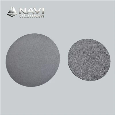
Innovational PEM electrolysers use porous titanium plates for structure and current transmission. Three-dimensional construction permits gas flow and evacuation and increases catalyst surface area. Pore size, joining, and porosity must match the catalytic system's needs.
Water flows through holes under 10 micrometres due to capillary pressure, but gas bubbles are trapped and cannot operate. Large holes exceeding 50 micrometres remove gases readily but degrade the material by providing the catalyst less binding surface. Modern best practices include bi-modal or gradient pore size distributions, with larger holes in the bulk substrate to transport gases and smaller pores near the catalyst interface to guarantee coating adherence and spread.
Small holes under 10 micrometres provide significant capillary pressure, which moves water but traps gas bubbles and prevents them from operating. Large holes above 50 micrometres remove gases easily but weaken the material by giving the catalyst less surface area to cling to. The best practices nowadays include bi-modal or gradient pore size distributions, with larger holes in the bulk substrate to transport gases and smaller pores at the catalyst contact to ensure coating adhesion and spread.
Manufacturing processes affect porous titanium's structure and characteristics. Sintered titanium powder provides equally distributed connected holes but no complicated gradient structures. You can accurately regulate the three-dimensional design of pores via additive manufacturing, making pore networks superior for particular purposes. Actually, correctly designed porous titanium anodes reduce cell voltage by 40 to 80 mV compared to solid titanium plates with mesh architectures. Because they enhance current and mass flow.

Surface Roughness and Texture Effects

Even solid titanium substrates have surface roughness that impacts contact and electrochemical performance. The optimal surface roughness is 0.8 to 2.5 micrometres to maximise contact area and minimise transport-blocking tortuosity. Surfaces smoother than Ra 0.5 micrometres bond poorly to coatings, whereas surfaces rougher than Ra 3.0 with extensive cracks trap gas bubbles and hinder diffusion.
Both roughness and surface texture design important. Planned textures with controlled directionality are better than abrasive blasting roughness. Gas bubbles remain less on active surfaces near edges or collecting channels, lowering voltage loss when blocking an active site. Laser texturing and electro-discharge machining may optimise surface patterns 15–25 mV better than randomly textured surfaces with the same average roughness.
Nearness of precious metal catalyst particles to titanium substrate impacts electron transport to active sites. High-resistance junctions at voltage-dropping areas reduce system efficiency due to poor contact. Because reactants and products pass through porous catalyst layers, the problem worsens. Excess substrate contact sites are prevented.
Advanced coatings maximise substrate contact and porosity with controlled particle size distribution and deposition characteristics. Thermal spray doesn't moisten substrates like ultrasonic coating. Spreading the catalyst increases contact density. Layered coatings increase structure. First layers adhere better to substrates, whereas last layers are electrochemically active.

How Titanium Anode Transition Layers Reduce Electrical Loss in PEM Systems
Transition layers, one of the biggest developments in titanium anode technology in the previous decade, reduce interfacial resistance and improve durability. These designed interlayers overcome key materials compatibility difficulties that hindered PEM electrolyser anode performance and lifespan.
Conductivity Enhancement Through Layer Engineering

Transition layers provide low-resistance electron transport between the titanium substrate and catalyst layer. Native titanium oxide on titanium surfaces is semiconducting and less conductive than metallic titanium. This oxide layer, generally 3-10 nanometres thick on freshly prepared surfaces, thickens and increases contact resistance under PEM anode oxidative conditions.
Oxidation-resistant conductive transition layers create durable, highly conductive contact. Titanium nitride is highly electrically conductive (10⁶ S/m) and stable in acidic and oxidative conditions. Since the TiN layer is a conduction channel and diffusion barrier, oxygen cannot oxidise titanium.
Experimental results on anodes with and without TiN transition layers demonstrate a large performance gap. Properly placed TiN interlayers lower contact resistance from 35–50 mΩ·cm² for bare titanium to 3–8 mΩ·cm². Reduced resistance at 2–3 A/cm² PEM current densities leads to 60–120 mV lower cell voltage and 3–5% efficiency increases, depending on operating conditions, while improving electrical uniformity across the electrode interface.

Stress Management and Delamination Prevention

Electrolyser temperature changes cause mechanical stress at interfaces due to material thermal expansion mismatch. Titanium has a thermal expansion coefficient similar to 8.6 × 10⁻⁶ K⁻¹, whereas iridium-based catalysts have a range of 6.4-6.8. Differential expansion causes interfacial shear forces that may surpass the adhesion strength of poorly constructed interfaces, causing delamination during heating from ambient to 60-80°C.
Gradient transition layers with progressive thermal expansion coefficients spread stress over numerous surfaces. A three-layer Ti-TiN-Ta₂O₅ system bridges the substrate-catalyst gap with intermediate expansion coefficients. These structures' finite element modelling reveals stress concentration factors lowered by 60-70% compared to direct catalyst deposition, improving coating adherence and lifespan.
The anode environment in PEM electrolysers is very difficult-acidic pH approaching 1-2, electrical potentials reaching 1.6 V against the reversible hydrogen electrode, and continual exposure to generated oxygen and reactive oxygen intermediates. Most materials quickly corrode at these circumstances, and few are stable enough for long-term use. Transition layer materials must resist disintegration and sustain protective performance for 40,000–80,000 hours in commercial applications. Under accelerated test circumstances simulating 10,000 hours of operation, tantalum oxide dissolves below 1 nanogram per square centimetre every hour. Transition layers maintain low interfacial resistance and prevent substrate corrosion throughout the electrolyzer's lifespan due to their amazing durability.

High-Efficiency Titanium Anode Design for Low-Voltage PEM Electrolyzers
A comprehensive anode design that covers all voltage loss causes is needed to achieve industry-leading PEM electrolyser efficiency. Most sophisticated systems combine optimised substrate design, carefully built transition layers, and precisely regulated catalyst deposition to minimise resistance, maximise active area use, and assure long-term stability.
Integrated Design Approach

Leading manufacturers combine substrate, transition layers, and catalyst coating into their design approaches rather than optimising each component separately. Design configurations that minimise total overpotential are found by modelling electron flow, mass transport, and electrochemical processes concurrently. This systems-level technique finds non-obvious optimisations that component-level design cannot.
Simulation results guide selection of substrate porosity profiles, transition layer thicknesses, and catalyst loading distributions for titanium anode to achieve balanced performance. Regions of high current density receive enhanced catalyst loading and optimized transition layer properties, while lower-activity regions employ more economical configurations. The result delivers performance approaching uniformly high-specification designs while reducing precious metal loading by 30-60%, substantially lowering system cost without sacrificing efficiency.
The translation of advanced designs into manufactured products requires precise process control and validation at each step. Surface preparation procedures establish the foundation, with cleaning, etching, and conditioning steps preparing the titanium substrate to receive subsequent layers. Even minor contamination or inadequate surface activation creates defects that propagate through subsequent processing, ultimately degrading interface quality.
Transition layer deposition employs vacuum-based physical vapor deposition or thermal chemical vapor deposition techniques that enable atomic-level control over composition and microstructure. Process parameters, including temperature, pressure, deposition rate, and substrate bias voltage, all influence the resulting layer properties. Manufacturing protocols developed through extensive experimentation establish the parameter windows that consistently produce high-quality interfaces meeting specification requirements.


Final catalyst application completes the anode fabrication, with loading, distribution, and adhesion all critically dependent on the quality of underlying layers. Advanced facilities employ multi-station processing with in-line quality control that monitors thickness, composition, and adhesion at each stage. Statistical process control ensures that production anodes meet the stringent requirements necessary for reliable long-term operation in commercial electrolyzers, while minimizing manufacturing variation between production batches and individual components.
Comprehensive testing processes ensure anodes operate and last as planned. Contact resistance fulfils standards, generally below 10 mΩ·cm² for high-performance applications, as confirmed by first electrical testing. Oxygen evolution performance is assessed in simulated PEM circumstances across the working current range, using 2 A/cm² voltage as the baseline.
Accelerated lifespan testing stresses anodes over weeks instead of months. Extended constant-current operation, potential cycling for start-stop simulation, and thermal cycling for mechanical stability evaluation are protocols. Good anodes retain voltage within 20 mV of starting values after 5,000-10,000 hours of accelerated testing, whereas poor designs degrade within 1,000-2,000 hours.


The best performance verification is in-service PEM electrolyser validation. Operational data from megawatt-scale field installations shows efficiency, dependability, and longevity. Advanced interface engineering anodes produce cell voltages 80–150 mV lower than prior designs with comparable current density, improving system efficiency by 4–7%. Over the multi-decade lifespans of hydrogen production plants, these increases cut power usage and provide economic value, while reducing cumulative operating expenses, supporting higher annual hydrogen output, and improving overall investment returns under continuous large-scale production conditions.
Conclusion
PEM electrolyser efficiency and durability depend on the titanium anode substrate-catalyst contact. Modern anodes attain interfacial resistance levels below 10 mΩ·cm² and consistent performance for 10,000+ hours by methodical engineering of surface features, transition layers, and deposition procedures. Advanced PEM systems can reach cell voltages near theoretical minimums, maximising green hydrogen generation efficiency.
Materials science and electrochemical engineering collaborated to create multi-layer anode architectures using titanium substrates. Future interface designs will reduce precious metal loadings while maintaining or enhancing performance. Optimised titanium anode interfaces will boost economic and environmental advantages as the hydrogen market grows and PEM electrolysis develops to gigawatt deployment levels.
fAQ
1. What voltage reduction can I expect by upgrading to advanced interface-engineered titanium anodes?
Optimally constructed titanium anodes with optimised interface layers lower cell voltage by 80-150 mV at 2 A/cm², according to field data from PEM electrolysers. This improvement is due to lower contact resistance (35-50 mΩ·cm² to 3-8 mΩ·cm²), improved current distribution, and greater mass transfer. The voltage advantage varies on operating circumstances, but efficiency increases of 4-7% are usual, saving significant power costs throughout system lifespan.
2. How do transition layers improve titanium anode durability in acidic PEM environments?
Titanium nitride and tantalum oxide transition layers safeguard anodes and enhance their lifespan. These layers protect the titanium substrate from acidic electrolyte corrosion and oxidation, which would increase electrical resistance. Multi-layer transition systems avoid temperature cycle delamination by managing substrate-catalyst thermal expansion mismatch with gradient composition. Properly constructed transition layers keep anodes stable for 10,000+ hours vs 2,000-3,000 hours without them.
3. Why does surface roughness matter for titanium anode performance in PEM systems?
Controlled surface roughness enhances titanium substrate-catalyst layer contact area, lowering interfacial electrical resistance and enhancing adhesion. Arithmetic average roughness (Ra) values of 0.8-2.5 micrometres are ideal for contact and mechanical interlocking without trapping gas bubbles or creating significant tortuosity. Engineered surface textures with directed patterns may also steer oxygen bubble development away from active locations, decreasing coverage-related voltage losses. Textured surfaces and transition layers reduce contact resistance to below 10 mΩ·cm², reducing efficiency loss in PEM electrolysers.
Ready to Reduce Voltage Loss in Your PEM Systems with Advanced Titanium Anode Technology?
NAVI Titanium delivers cutting-edge platinum/iridium-coated titanium anode solutions specifically engineered for maximum efficiency in PEM water electrolysis applications. Our proprietary interface engineering technology reduces precious metal loading by 30-60% compared to conventional designs while maintaining superior performance across 10,000+ hours of continuous operation. With adjustable Pt/Ir coating from 0.05-0.5 mg/cm² and advanced gradient transition layers, NAVI Titanium anodes optimize your system for the lowest possible voltage loss and highest energy efficiency.
Partner with a trusted titanium anode supplier that combines university-level research capabilities with proven mass production expertise. NAVI Titanium Metal Technology Co., Ltd works directly with electrolyzer manufacturers and hydrogen production facilities worldwide to deliver customized anode solutions that reduce operational costs and improve system reliability.
Contact our technical sales team today to discuss your specific PEM electrolyzer requirements and discover how our fourth-generation low-precious metal composite coatings can enhance your system performance. Email us at sales@navititanium.com for technical specifications, performance data, and project quotations.
References
1. Carmo, M., Fritz, D. L., Mergel, J., and Stolten, D. (2013). "A Comprehensive Review on PEM Water Electrolysis." International Journal of Hydrogen Energy, Volume 38, Issue 12, pp. 4901-4934.
2. Bernt, M., Siebel, A., and Gasteiger, H. A. (2018). "Analysis of Voltage Losses in PEM Water Electrolyzers with Low Platinum Group Metal Loadings." Journal of The Electrochemical Society, Volume 165, Issue 5, pp. F305-F314.
3. Ayers, K. E., Renner, J. N., Danilovic, N., Wang, J. X., Zhang, Y., Maric, R., and Yu, H. (2016). "Pathways to Ultra-Low Platinum Group Metal Catalyst Loading in Proton Exchange Membrane Electrolyzers." Catalysis Today, Volume 262, pp. 121-132.
4. Mo, J., Kang, Z., Yang, G., Retterer, S. T., Cullen, D. A., Toops, T. J., Green Jr., J. B., and Zhang, F. Y. (2016). "Thin Liquid/Gas Diffusion Layers for High-Efficiency Hydrogen Production from Water Splitting." Applied Energy, Volume 177, pp. 817-822.
5. Hegge, F., Moroni, R., Trinke, P., Bensmann, B., Hanke-Rauschenbach, R., Thiele, S., and Vierrath, S. (2020). "Three-Dimensional Microstructure-Resolved Modeling of Proton Exchange Membrane Electrolysis Performance." Journal of Power Sources, Volume 465, Article 228269.
6. Schuler, T., Ciccone, J. M., Krentscher, B., Marone, F., Peter, C., Schmidt, T. J., and Boillat, P. (2019). "Hierarchically Structured Porous Transport Layers for Polymer Electrolyte Water Electrolysis." Advanced Energy Materials, Volume 10, Issue 2, Article 1903216.